
Installing a PTO shaft for the first time is straightforward when you follow the steps in the right order. The process takes under ten minutes when the shaft is correctly specified and the equipment is prepared properly. When something is wrong — the yoke will not seat, the shaft bottoms out, or the operating angle looks steep — the installation itself tells you what needs to be adjusted before a single revolution is turned.
This guide walks through every stage: the checks to complete before touching the shaft, the correct connection sequence, the adjustments that determine whether the shaft performs reliably for years or fails within a season, and the five mistakes that first-time installers most commonly make. Whether you are fitting a new shaft to a new implement or replacing a worn shaft on familiar equipment, this sequence applies.
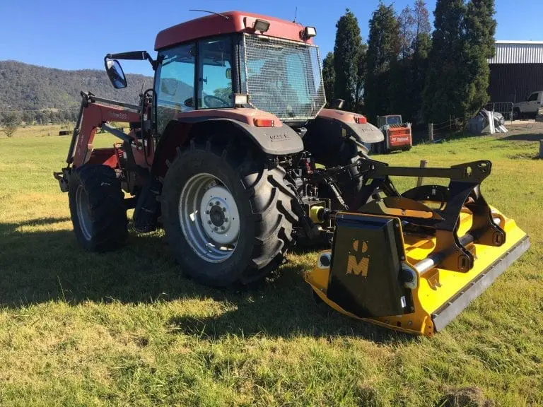
A correctly assembled PTO shaft ready for installation — verify all components before connecting to the tractor
Before You Begin: 5 Pre-Installation Checks
Running through these checks before connecting the shaft takes less than five minutes and prevents the majority of first-time installation problems.
Confirm spline match at both ends
Slide the tractor-end yoke partway onto the PTO stub by hand — it should move smoothly without binding. Do the same with the implement-end yoke on the gearbox input shaft. If either yoke resists or rattles with excessive play, you have a spline mismatch that must be resolved before installation. See our range of agricultural machinery PTO drive shafts to verify the correct spline series for your application.
Verify shaft length against the equipment
With the implement attached but the PTO shaft not yet connected, raise the implement to its highest transport position and measure the distance between the tractor PTO stub end and the implement gearbox input stub end. The shaft’s compressed (closed) length must be shorter than this distance by at least 25mm. Lower to working height and confirm the shaft will not run out of telescopic travel.
Grease the splines before connection
Apply a film of lithium EP2 grease to the tractor PTO stub splines and the implement input shaft splines before sliding the yokes into position. Dry engagement causes fretting corrosion from the first revolution — a microscopic wear mechanism that progressively loosens the fit and eventually allows the yoke to shift under torque.
Check that the safety shield is complete
Before installation, verify that the safety shield is present, undamaged, and that its restraining chains or clips are attached and in good condition. A shield that is cracked, missing segments, or has seized bearings needs replacement before the shaft is put into service.
Confirm overload protection is fitted and adjusted
If the shaft is equipped with a slip clutch, verify the spring adjustment nut is set to the torque level appropriate for your implement. If shear bolts are used, confirm the correct grade and diameter are installed. Never begin work with an overload device that has been bypassed or incorrectly adjusted.
Step-by-Step Installation: The Correct Sequence
⚠ Safety first: Ensure the tractor engine is off and the PTO lever is in the disengaged position before beginning. Wait for any residual implement rotation to stop completely before approaching the driveline area.
Connect the tractor end first
Hold the shaft with the tractor-end yoke facing the PTO stub. Align the yoke splines with the stub splines and push firmly inward until you feel and hear the locking pin snap into the stub’s locking groove. Tug the yoke outward firmly — it should not release. If it pulls free without pressing the locking pin button, re-seat it and tug again. Never proceed until this connection is confirmed secure.
Set the shaft to working length
With the tractor end connected and the shaft hanging from the PTO stub, allow the shaft to extend toward the implement input shaft under its own weight. The telescopic section should be partially extended — if it is fully extended before the implement-end yoke reaches the input shaft, the shaft is too short for this equipment combination. If the shaft needs to be compressed more than halfway to reach the input shaft, it may be longer than ideal. The optimal working length has the shaft at 50–75% extension in the working position.
Connect the implement end
Guide the implement-end yoke onto the gearbox input shaft splines. Push firmly until the locking mechanism engages. For push-pin yokes, the pin clicks into the groove. For interfering bolt yokes, tighten the bolt to the torque specified in the shaft documentation. For yokes with a spring-loaded collar, hold the collar retracted while seating and release it to lock. Tug the yoke outward to confirm engagement.
Verify universal joint phasing
Stand to one side and sight along the shaft axis. The input yoke ears (at the tractor end) and the output yoke ears (at the implement end) must be in the same plane — both pairs of ears pointing in the same direction when the shaft is viewed end-on. Incorrect phasing creates a cyclic speed variation that vibrates the entire driveline at twice PTO frequency and dramatically accelerates U-joint wear.
Most replacement shafts from reputable manufacturers are assembled with correct phasing. However, if a shaft has been disassembled for tube replacement or cleaning, phasing must be re-verified before use. To correct incorrect phasing, separate the telescopic section and rotate one tube 90 degrees relative to the other before reassembly.
Anchor the safety shield restraints
Connect the shield restraining chains or clips to fixed anchor points — one end to the tractor chassis or hitch frame, the other end to a fixed point on the implement frame. The chains must be taut enough to prevent the shield from rotating with the shaft, but with enough slack to allow the telescopic section to extend and compress during operation. Do not attach the chains to any moving part of the tractor or implement.
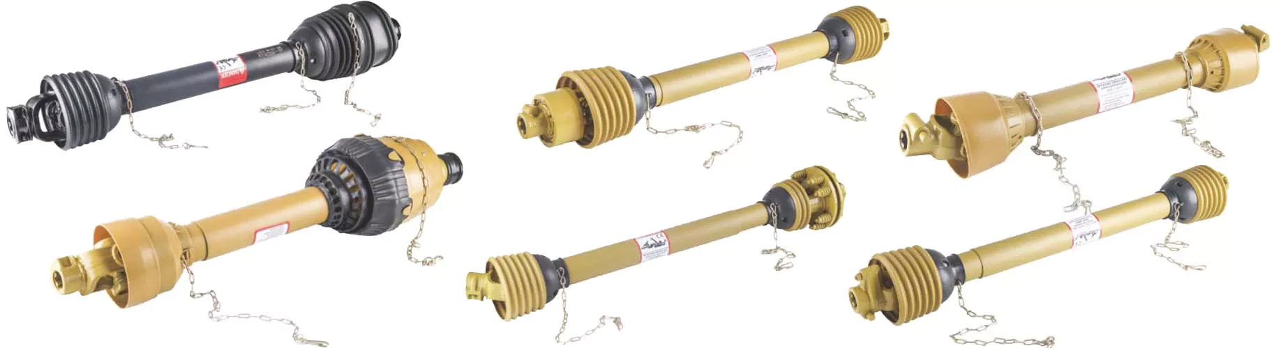
Different shaft configurations require the same installation sequence — the locking mechanism type varies but the connection order is always tractor end first
Check operating angle at working height
Lower the implement to its normal working height. Visually assess the angle between the tractor PTO stub and the implement input shaft. The shaft should be as close to straight as possible. For standard cross-type U-joints, the angle must not exceed 15 degrees continuously. If the angle appears steep, try adjusting the implement’s top link length or category hitch adjustment to bring the input shaft closer to horizontal. For applications where the geometry cannot be improved below 15 degrees, a wide-angle joint PTO shaft rated for higher operating angles is the correct solution.
Grease all fittings before first use
Even if the shaft came pre-greased from the factory, apply fresh grease to all U-joint fittings and the telescopic section before the first use. New shafts may have sat in storage, and factory grease may have migrated. Grease until fresh grease appears at all four bearing cup seals on each joint, and apply a thin film to the profile surfaces inside the telescopic tubes.
First-run check: start at idle and listen
Start the tractor and engage the PTO at idle speed. Before increasing RPM, listen for any vibration, clicking, or scraping sound. Watch the shaft for any visible wobble. Confirm the safety shield remains stationary while the shaft rotates. Only increase to working speed after confirming the driveline is running smoothly at idle.
Inspect the Connected Components at the Same Time
A new PTO shaft installation is an ideal moment to inspect the full driveline and positioning system. Components that are borderline serviceable will stress the new shaft and may cause early failure.
Implement gearbox
Check oil level and condition. Rotate the input shaft by hand and listen for grinding or roughness. Inspect input shaft splines for wear or chipping. A damaged gearbox transmits vibration directly into the new shaft’s U-joints.
Tractor PTO output bearing
Grip the PTO stub and check for radial wobble with the tractor off. A worn output bearing creates a constantly changing operating angle at the tractor-end U-joint — the most damaging form of misalignment for bearing life.
Three-point hitch & hydraulics
Verify the hitch lift arms rise and lower smoothly and hold position under load. A hitch that drifts down under load increases the PTO shaft operating angle during work. Manufacturers that produce both drivetrain components and hydraulic equipment — such as ssj-group.com — provide integrated technical resources on how these systems affect each other.
5 Common Installation Mistakes to Avoid
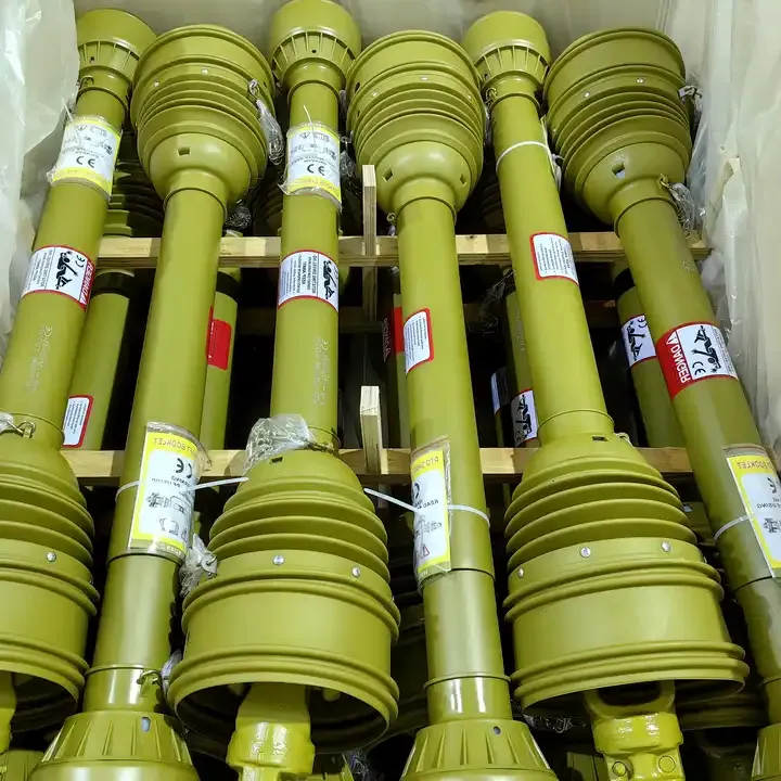
Correct installation includes properly anchored shield chains and correctly positioned overload protection
Connecting the implement end first. When the implement end is connected first, adjusting the shaft length to the correct working extension is far more difficult — you are working against the weight of the shaft hanging from the implement. Always tractor end first, then implement end.
Not confirming the locking pin has seated. A yoke that sits on the splines without the locking pin in its groove looks and feels secure until the first load is applied. One tug test takes two seconds and confirms the connection. Many driveline separation incidents happen because this step was skipped.
Skipping the operating angle check. A shaft installed at too steep an angle will fail the U-joints within one season regardless of how well it is maintained. The installation is the only opportunity to adjust the hitch geometry before problems develop.
Attaching shield chains to moving parts. A chain attached to a lift arm, hydraulic cylinder rod, or any component that moves relative to the tractor will either snap the chain under extension or pull the shield against the spinning shaft — neither outcome is acceptable.
Skipping the idle test before going to full speed. An incorrectly phased shaft, a partially seated yoke, or a shield bearing seized against the shaft will all reveal themselves immediately at idle with no load. The same problem at full PTO speed and under cutting load is far more destructive and dangerous.
Removing the PTO Shaft Safely
Removal follows the reverse of installation, with the same safety requirements:
- Engine off. PTO fully disengaged. Wait for all implement rotation to stop.
- Disconnect shield restraining chains at both ends.
- Press the locking pin button on the implement-end yoke and slide the yoke off the implement input shaft.
- Support the shaft weight with one hand while pressing the locking pin button on the tractor-end yoke and sliding the yoke off the PTO stub.
- Lower the shaft to the ground — never drop it. A shaft dropped from PTO height can bend a tube or damage U-joint bearing cups.
- Wipe the shaft clean, re-grease the telescopic section and U-joint fittings, and store the shaft horizontally in a dry location.
For questions about shaft selection, replacement specifications, or sourcing a shaft matched to your tractor and implement combination, contact our team. Providing your tractor model, implement type, and the PTO stub spline count allows us to identify the correct shaft series, length, and overload protection in a single exchange.